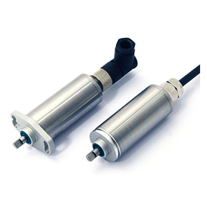
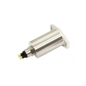
TPS280DP Contactless Throttle Position Sensor with Dual Output
Throttle position sensors, otherwise known as TPS, are designed to track the throttle position of a vehicle. This sensor is able to closely monitor the throttle as it is typically directly positioned on the butterfly spindle, or shaft, of the vehicle.
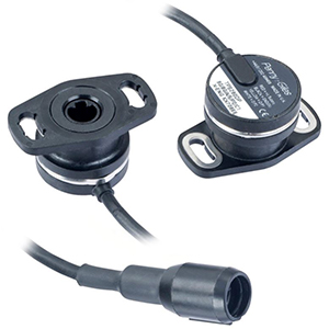
A variant of the popular, contactless rotary throttle positioning sensor range, this dual output throttle position sensor uses a factory programmable non-contact, Hall-effect sensor system.
- Electrically interchangeable with potentiometers
- More than 9x the life of a potentiometer
- Extremely low signal noise, for the life of the sensor
- Will operate from -40 to +140°C, with excursions to +170°C
- Sealed to withstand high pressure wash-downs (IP69K)
- Mechanically interchangeable with potentiometers on 32mm mountings
- Standard output is dual channel
- Configurable output direction, for left or right fitment
- Measurement range from 20 to 360° in 1° increments
- 12-bit resolution (0.025%) over the angular range
- Analogue (0.5 – 4.5 or 0.1 – 4.9Vdc) or PWM outputs
TPS280DP is designed as the modern alternative throttle positioning sensor (TPS) to rotary potentiometers fitted on high-performance race car and motorcycle induction systems.
Replacing a potentiometer with the TPS280DP will eliminate premature failure due to electrical noise – caused by potentiometer wear. TPS280DP is life tested to 30-million cycles (60 million operations), more than NINE TIMES that of a potentiometer in this application.
TPS280DP is mechanically interchangeable with most existing throttle position sensors using 32mm mounting centres and is designed to interface with most common throttle body D-type spindles. The sensor has a choice of 200 or 500mm cable lengths, with or without an MSS4P Mini Sure-Seal connector fitted to the FDR-25 sheathed spec 55A cable. With sealing to IP69K, it is also able to withstand high pressure wash-downs.
The TPS280DP operates from 5Vdc (and 9-30Vdc) and is factory programmed to allow a wide range of configurations.
Electrical
Measurement range: 20 to 360 in 1° increments
Supply voltage Vdc: 9 to 30 (unregulated) and 5 ±0.5 (regulated)
Over voltage protection Vdc: Up to 40 (-40 to +60°C)
Maximum supply current mA: <25
Reverse polarity protection: Yes
Short circuit protection:
Output to GND: Yes
Output to supply: In 5V regulated mode only
Power-on settlement time S:<1
Resolution: % 0.025 of measurement range (12 bit)
Non-linearity:* % <±0.4
Temperature coefficient ppm/°C <±30 in 5V supply mode: <±90 in 9-30V supply mode
*Non-linearity is measured using the Least-Squares method on a computerised calibration system
Options
Measurement range (angle): Select from 20° to 360° in 1° increments (factory programmed) for each output channel
Output: Analogue voltage (An) or PWM (Pn)
Output direction: Both clockwise, both anticlockwise or one CW, one ACW
Cable length: m 0.2 or 0.5
Connector: Not fitted (C0) or Mini Sure Seal MSS4R fitted (C1)
OEM options: Outputs can be programmed to provide: non linear laws; switch outputs; clamp voltages; different output phasing CH1/CH2; faster input/output delay; extended analogue range; and output mapping for potentiometer replacements.
Content missing
Related Products
-
Intrinsically safe H505 is CSA approved for use in potentially explosive gas/vapour and dust atmospheres. The H505 is an affordable, durable, high-accuracy rotary sensor desig...
H505 Rotary Position Sensor
Intrinsically safe H505 is CSA approved for use in potentially explosive gas/vapour and dust atmospheres. The H505 is an affordable,…
-
The intrinsically safe M114 is an ATEX and IECEx mining approved affordable, durable, high-accuracy position sensor. Derived from the M114 Waterproof Linear Position Sensor
The intrinsically safe M114 is an ATEX and IECEx mining approved affordable, durable, high-accuracy position sensor. Derived from the M101…
-
Intrinsically safe 350bar G623 is CSA approved for use in potentially explosive gas/vapour atmospheres. The G623 is designed for industrial and scientific feedback application...
G623 Submersible IP68 Large Angle Tilt Sensor
Intrinsically safe 350bar G623 is CSA approved for use in potentially explosive gas/vapour atmospheres. The G623 is designed for industrial…
-
A dual-redundant output, contactless, rotary position sensor with integrated 6-way connectors, using a factory programmable Hall-effect sensor system.
- Contactle...
SRH220DR Rotary Position Sensor Dual-redundant
A dual-redundant output, contactless, rotary position sensor with integrated 6-way connectors, using a factory programmable Hall-effect sensor system. Contactless - Hall-effect technology…
- Contactle...
-
Intrinsically safe H505 is CSA approved for use in potentially explosive gas/vapour and dust atmospheres. The H505 is an affordable, durable, high-accuracy rotary sensor desig...
H505 Rotary Position Sensor
Intrinsically safe H505 is CSA approved for use in potentially explosive gas/vapour and dust atmospheres. The H505 is an affordable,…
-
The intrinsically safe M114 is an ATEX and IECEx mining approved affordable, durable, high-accuracy position sensor. Derived from the M114 Waterproof Linear Position Sensor
The intrinsically safe M114 is an ATEX and IECEx mining approved affordable, durable, high-accuracy position sensor. Derived from the M101…
-
Intrinsically safe 350bar G623 is CSA approved for use in potentially explosive gas/vapour atmospheres. The G623 is designed for industrial and scientific feedback application...
G623 Submersible IP68 Large Angle Tilt Sensor
Intrinsically safe 350bar G623 is CSA approved for use in potentially explosive gas/vapour atmospheres. The G623 is designed for industrial…
-
A dual-redundant output, contactless, rotary position sensor with integrated 6-way connectors, using a factory programmable Hall-effect sensor system.
- Contactle...
SRH220DR Rotary Position Sensor Dual-redundant
A dual-redundant output, contactless, rotary position sensor with integrated 6-way connectors, using a factory programmable Hall-effect sensor system. Contactless - Hall-effect technology…
- Contactle...

